Key Takeaways for Mission-Critical Underfill
- Flip chip underfill is an epoxy encapsulant that stabilizes solder bumps, redistributes thermomechanical stress from CTE mismatch and protects interconnects from moisture and shock in demanding environments.
- Capillary underfill remains the preferred process for aerospace, defense and medical programs because of material maturity, proven reliability and rework flexibility compared with no-flow and molded options.
- Material properties such as CTE, modulus and glass transition temperature must be balanced together. Focusing on a single property does not ensure reliable performance across temperature cycles.
- Process controls including dispense volume, viscosity selection, plasma treatment, flux residue management and tuned curing profiles are essential to reduce voids, delamination and yield loss.
- Pro-Active Engineering integrates DFM, advanced packaging and certified quality systems under one domestic ITAR-compliant partner to de-risk flip-chip programs from prototype through production. Request a quote to discuss specific requirements.
Comparing Capillary, Molded and No-Flow Underfill Processes
Each underfill process type follows a distinct sequence of steps with different implications for throughput, rework and suitability in high-reliability programs.
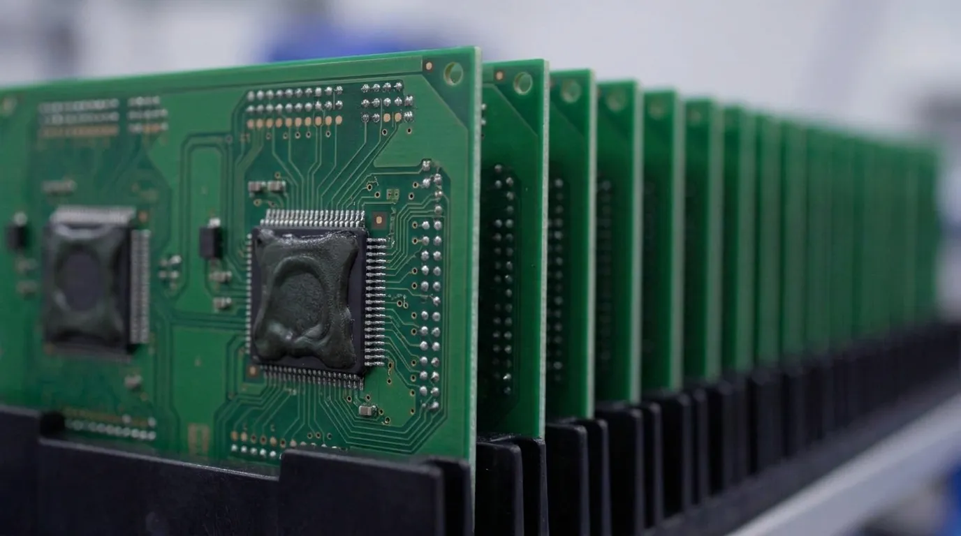
Capillary underfill (CUF) is the most established method for high-reliability applications. Epoxy is dispensed at the chip edge after solder reflow and flows beneath the die through capillary action, followed by thermal curing to cross-link the resin.
- Dispensed post-reflow at the die perimeter
- Flows under the chip by capillary action, with no external pressure required
- Requires a separate cure step
- Provides proven mechanical strength and material maturity
- Preferred for programs that require high reliability and rework access
No-flow underfill (NUF) is applied before reflow, simultaneously with solder paste. It cures during the reflow step, which eliminates the separate post-reflow dispense and capillary-flow operations required by CUF.
- Applied before component placement
- Cures during standard solder reflow
- Reduces total process steps and improves throughput
- Thixotropic, non-sag formulations are preferred to maintain fillet geometry before reflow
- Less suitable for assemblies that require post-assembly rework
Molded underfill (MUF) integrates gap filling and package molding in a single step. Both filling and molding are completed simultaneously using packaging molds, which makes MUF well suited for high-volume production with consistent coverage.
- Gap filling and encapsulation occur in one molding step
- Delivers uniform coverage across the package
- Supports high-volume production efficiency
- Rework is limited once molding is complete
- Requires tooling investment, which reduces flexibility for low-volume or high-mix programs
Aerospace, defense and medical programs with low-to-mid volume and high complexity generally favor capillary underfill because of its material maturity and rework potential.
Balancing CTE, Modulus and Tg in Underfill Materials
CTE, glass transition temperature (Tg) and modulus in underfill materials are interdependent. Optimizing any single property in isolation fails to address the full thermomechanical response across temperature cycles.
Silicon dies exhibit a CTE near 2.6 ppm/°C, while organic substrates range from 15 to 18 ppm/°C. Underfill bridges this mismatch by acting as a compliant mechanical system. Below Tg, underfill remains relatively stiff. Above Tg, it becomes more flexible, which directly affects warpage during reflow, cure and post-cool-down stress retention.
The tradeoff between modulus and Tg is a central design decision. Higher Tg often comes with higher modulus, which raises stress on bumps and low-k dielectrics.
Nano-silica fillers are added to underfill formulations to lower CTE, raise modulus and improve thermal conductivity while maintaining the low viscosity needed for capillary flow. For advanced packaging architectures with multiple material interfaces, die attach film layers with intermediate CTE and controlled Young’s modulus act as stress buffers between the chiplet, underfill and epoxy molding compound, which creates a graduated stress transition instead of a single high-stress interface.
These material options, including fillers, films and base resin chemistry, must be balanced together. Tg, modulus and CTE must align with the package architecture, bump design and operating temperature profile of the target application.
Process Controls That Protect Yield and Reduce Voids
Selecting the right underfill material establishes the foundation for reliability. Translating those material properties into field performance depends on process execution. Process control at each stage of underfill application directly determines yield and long-term reliability.
Dispense volume control is a primary yield lever. Optimal fillet volume provides continuous coverage on all four sides of the die, full gap fill without voids and moderate climb height while avoiding creep onto the die top or neighboring components. Insufficient fillet volume leaves corner solder joints without structural support, which accelerates fatigue failure under thermal cycling. Excess volume introduces cleanup steps that create manufacturing bottlenecks.
Viscosity selection governs capillary flow behavior. Equipment can process underfills across a broad viscosity range, which enables formulation choices matched to bump pitch, gap height and substrate surface energy. Lower-viscosity compounds are preferred for capillary underfill to promote complete gap fill.
Plasma treatment before underfill dispense physically ablates contaminants, increases micro-roughness for mechanical interlocking and chemically activates surfaces. These effects improve adhesion and reduce delamination risk.
Flux residue management is critical for reliability. Incomplete flux residue removal can cause electrochemical migration and dendritic growth under bias. Trapped flux volatiles also create voids that impede thermal dissipation and signal integrity.
Curing profiles must match the specific formulation. Under-cure leaves a weak interface, while excessively high temperatures or fast ramp rates lock in stress that causes delamination. Multi-stage curing profiles are standard practice for high-reliability assemblies.
Validated process parameters during prototyping, using the same equipment and materials as production, provide the most reliable path to a smooth prototype-to-production transition.
Failure Modes and Reliability Testing for Regulated Programs
Failure mode knowledge guides both material selection and process control decisions for regulated-industry programs.
Voiding reduces the effective load-bearing area of solder joints. Voiding accelerates fatigue failure during thermal cycling, and mitigation includes stencil aperture optimization and reflow process control.
Delamination at the underfill-to-die or underfill-to-substrate interface can crack dies or break interconnects. CTE mismatch generates shear stress at interfaces during thermal cycling, and delamination occurs when adhesion strength is insufficient.
Fillet cracking is associated with high-modulus, high-Tg underfills that increase warpage and transfer stress into low-k dielectric structures. Fillet geometry and material selection both influence cracking susceptibility.
Solder joint fatigue under thermal cycling is characterized by progressive crack growth under cyclic shear loading, with cracks initiating at the solder-to-pad interface or intermetallic layers and propagating until electrical continuity is lost.
Inspection methods for regulated programs include:
- Scanning acoustic tomography (SAT), which non-destructively detects delamination and voids by identifying air gaps in ultrasonic images
- X-ray inspection for solder joint voiding and bump integrity
- Thermal cycling qualification per IPC-9701 and JEDEC JESD22-A104, using daisy-chain monitoring and Weibull analysis to predict characteristic life
DFM Practices for Reliable Flip-Chip Underfill
Early packaging decisions set the stage for yield, rework and schedule performance. Integrating DFM from the earliest design phase, with manufacturing engineering involved in material selection, bump layout and substrate stack-up, reduces the probability of late-stage failures.
Key DFM considerations for flip-chip underfill begin with bump pitch and gap height compatibility with the selected underfill viscosity, which determines whether the material can flow completely through the gap. Substrate surface finish and cleanliness directly affect adhesion strength at the underfill-to-substrate interface. Thermal pad and fillet clearance from neighboring components must be verified to prevent bridging or interference during dispense. The cure profile must also remain compatible with the full assembly thermal budget to avoid damage to temperature-sensitive components elsewhere on the board.
Pro-Active Engineering places design engineers and manufacturing engineers in the same workflow from day one. DFM review, sourcing and quality planning sit inside the design phase, not after layout completion. This structure eliminates the prototype-to-production disconnect that often generates late-stage manufacturability issues in fragmented supply chains.
Pro-Active Engineering operates an ITAR-compliant domestic facility with full traceability documentation and counterfeit avoidance protocols under SAE AS5553B. These measures address the compliance requirements of aerospace, defense and medical programs. Certifications including ISO 9001:2015, AS9100 and Nadcap accreditation provide the quality system infrastructure that regulated programs require. JCP certification and alignment with NIST 800-171 further support programs with controlled-data and export-compliance obligations.
Engineering teams that manage high-density flip-chip assemblies gain an advantage by consolidating design, advanced packaging and production under one accountable domestic partner. This approach reduces vendor fragmentation and the compliance exposure that comes with it.
Request a quote to discuss flip-chip assembly requirements with Pro-Active Engineering’s engineering team.
Conclusion: Key Decisions for Underfill and Assembly Partners
Underfill selection for flip-chip packaging requires evaluating the interdependent material properties discussed earlier, including CTE compatibility and modulus-Tg tradeoffs, alongside process type suitability and inspection requirements for the specific package architecture and operating environment.
Process control, including dispense volume, viscosity, plasma treatment, flux management and cure profile, determines whether material properties translate into field reliability. These controls must be validated during prototyping with production-equivalent processes so that the transition to volume manufacturing does not introduce new failure modes.
For aerospace, defense and medical programs, the assembly partner’s quality system, traceability infrastructure and domestic compliance posture carry the same weight as technical capability. Pro-Active Engineering combines advanced interconnect and packaging capabilities with certified quality systems and an integrated engineering-to-production workflow that de-risks programs from first prototype through full production.
Request a quote and connect with Pro-Active Engineering’s team to evaluate underfill and flip-chip assembly options for a specific program.
Frequently Asked Questions
Capillary, No-Flow and Molded Underfill Selection for High-Reliability Builds
Selection depends on production volume, rework requirements and package architecture. Capillary underfill is the most established option for high-reliability, low-to-mid volume programs because of its material maturity, proven mechanical performance and the ability to rework assemblies before cure. No-flow underfill reduces process steps and improves throughput, which suits higher-volume builds where rework access has lower priority. Molded underfill fits high-volume production with consistent package geometries, but tooling investment and limited rework access reduce practicality for complex or variable programs. Aerospace, defense and medical programs typically favor capillary underfill for its material maturity and compatibility with IPC and JEDEC qualification standards.
Reworkability Limits of Flip-Chip Underfill and Program Planning
Once underfill is fully cured, rework requires mechanical or chemical removal of the encapsulant, which risks damage to the die, substrate and neighboring components. Capillary underfill offers the most rework flexibility because it is applied post-reflow and can be selectively removed before cure if a defect is detected early. No-flow and molded underfill processes cure during or immediately after reflow, which significantly limits rework options. Program teams should account for reworkability requirements when selecting underfill type and should establish inspection checkpoints, including acoustic microscopy and X-ray, before cure to catch defects at the lowest-cost intervention point. Integrating rework planning into the DFM phase, rather than addressing it after production begins, reduces schedule and cost risk.
Supply Chain Traceability for Underfill in Regulated Industries
Aerospace, defense and medical programs require full traceability of materials, processes and inspection records throughout the assembly lifecycle. For flip-chip underfill, this requirement includes lot-level traceability of the underfill material, documentation of cure profiles and process parameters and records of inspection results from acoustic microscopy and X-ray. Counterfeit avoidance protocols, such as those defined in SAE AS5553B, apply to all components and materials in the assembly, including underfill formulations sourced from the supply chain. A domestic, ITAR-compliant assembly partner with a certified quality management system provides the documentation infrastructure and controlled processes that regulated programs require. Fragmented supply chains with multiple vendors increase the risk of traceability gaps and compliance exposure.
Material Tradeoffs for Underfill Above 125°C Operating Temperature
High-temperature applications above 125°C typically require underfills with elevated glass transition temperature to maintain mechanical stiffness and prevent softening during operation. Higher Tg formulations are generally associated with higher modulus values, which increase warpage, transfer more stress into low-k dielectric structures and raise the risk of fillet cracking and delamination. The tradeoff between bump stress protection and low-k dielectric stress must align with the specific package architecture and thermal cycling profile. Nano-silica fillers can adjust CTE and modulus independently to some degree, but no universal low-stress solution exists. Finite element simulation during the design phase helps engineering teams predict thermomechanical response and select underfill properties that balance reliability across all failure modes relevant to the application.
Request a quote to engage Pro-Active Engineering’s team on underfill material selection, DFM review and flip-chip assembly for mission-critical programs.