Last updated: April 17, 2026
Key Takeaways
- IPC standards such as IPC-6012, IPC-A-600, and IPC-A-610 define tolerances for fabrication, bare board inspection, and assembly, which protects prototype reliability.
- Class 3 requirements for aerospace, defense, and medical hardware call for 4 mil minimum trace/space and tight annular rings that exceed Class 2 industrial expectations.
- Recent updates in IPC-A-600M and IPC-6012F cover microvia testing, back-drilling, and automated inspection (AOI and AXI), which supports high-density prototypes.
- DFM practices that follow IPC-7351 land patterns, clear fiducials, and robust solder mask dams reduce issues such as annular ring breakout and QFN shorts.
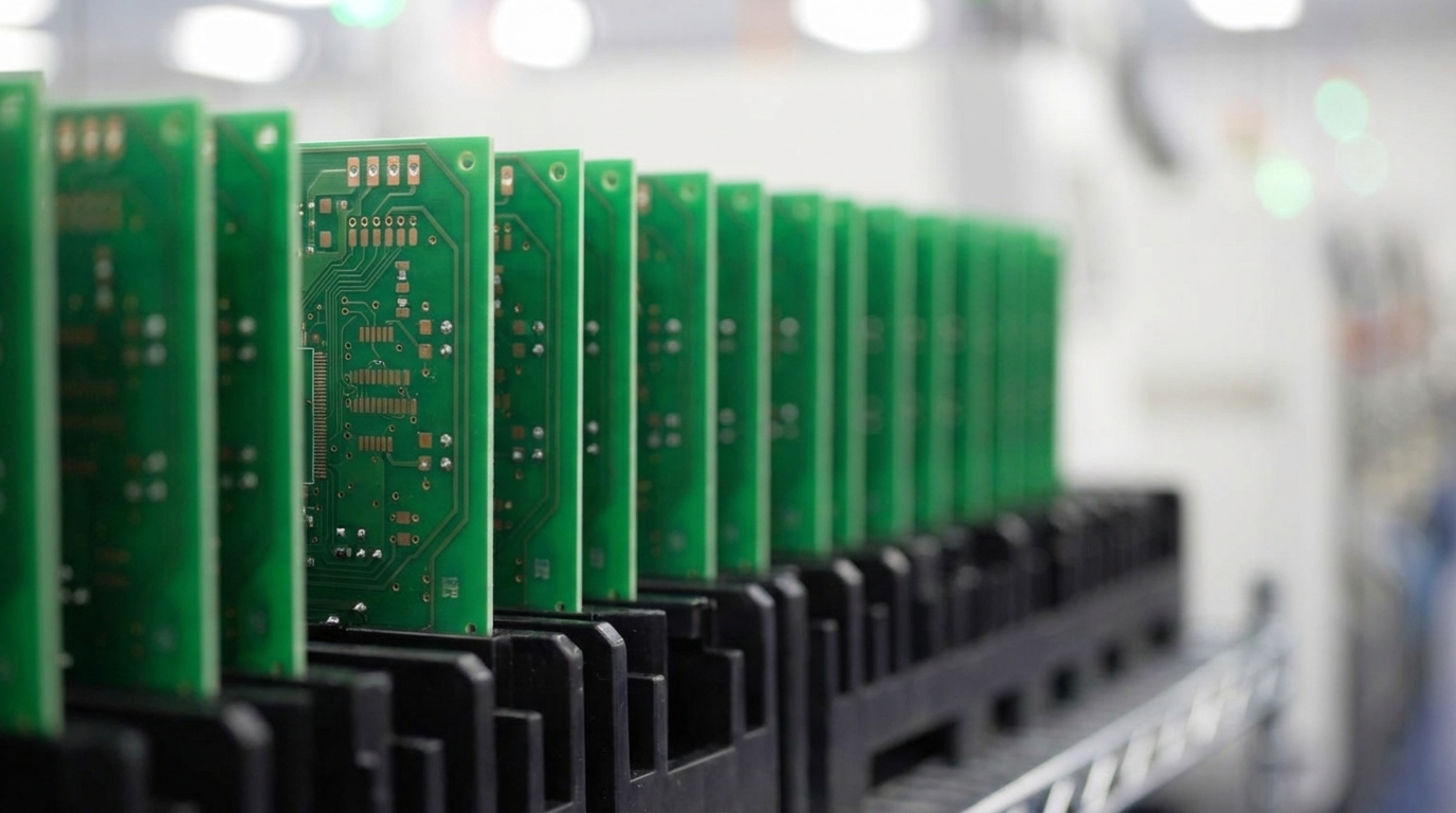
- Pro-Active Engineering delivers IPC Class 2 and Class 3 certified 2–5 day prototypes using full production processes; request a quote for a smooth path from prototype to production.
IPC Product Classes and Their Impact on Prototype Reliability
IPC standards classify PCBs into three product classes based on reliability needs and application criticality. These classifications guide manufacturing tolerances and inspection criteria during prototyping and production.
The following table shows how trace and space tolerances and annular ring requirements tighten as designs move from general electronics in Class 1 to mission-critical Class 3 applications.
| Product Class | Application | Trace/Space Tolerance | Annular Ring (External) |
|---|---|---|---|
| Class 1 | General electronics, toys | often 6–8 mil | 0.10 mm (4 mil) |
| Class 2 | Industrial controls and electronics | often 5–6 mil | 0.05 mm (2 mil) |
| Class 3 | Aerospace, defense, medical | 4 mil minimum | 0.051 mm (2 mil) |
Class 3 applications demand the highest reliability standards and tighter bow and twist limits than Class 2, along with insulation resistance ≥100 MΩ. These requirements support reliable performance under vibration, thermal cycling, and long service life in mission-critical environments.
Pro-Active Engineering holds IPC-A-610 Class 2 and Class 3 workmanship certification so your prototypes match production standards. Our 100% AOI inspection and flying probe testing validate compliance from day one and help avoid costly redesigns during scaling.
Essential IPC Standards Across the PCB Manufacturing Lifecycle
Now that the three product classes and their reliability expectations are clear, the next step is to connect them to specific IPC standards. Multiple IPC standards govern PCB design, fabrication, and assembly, and their combined use supports compliance from prototype through full production.
The table below maps each standard to its role in the manufacturing process and highlights what matters most during prototyping.
| Standard | Focus Area | Latest Revision | Key Prototyping Requirements |
|---|---|---|---|
| IPC-A-600M | Bare board acceptability | May 2025 | Visual inspection criteria and surface defect limits |
| IPC-6012F | Rigid board qualification | October 2023 | Performance specifications and material requirements |
| IPC-A-610J | Assembly acceptability | Early 2024 | Solder joint quality and component placement criteria |
| J-STD-001J | Soldering requirements | March 2024 | Soldering processes and material controls |
IPC-6012F adds detailed rules for back-drilled structures, surface finishes, copper wrap plating, and performance-based microvia testing, which are all crucial for dense, high-layer-count prototypes. IPC-A-600M broadens guidance on automated inspection methods such as AXI, AOI, SPI, ALT, and machine vision, so teams can validate boards more thoroughly and consistently.
Specialized addendums support niche applications. IPC-6012FS defines exceptions to IPC-6012F Performance Class 3 requirements for space and military avionics, while IPC-6012EM (2020) targets medical-grade boards.
Pro-Active Engineering maintains current certification to relevant IPC standards so your prototypes align with the latest revisions. Our Speed Shop applies these standards during every build to deliver production-ready prototypes that scale cleanly to volume manufacturing.
How IPC-6012, IPC-A-600, and IPC-A-610 Work Together
Clear separation of scope across IPC-6012, IPC-A-600, and IPC-A-610 prevents compliance gaps and supports complete prototype validation.
| Standard | Scope | Inspection Focus | Application Stage |
|---|---|---|---|
| IPC-6012 | Performance requirements and manufacturing specifications | Electrical performance and material qualification | Fabrication design |
| IPC-A-600 | Visual acceptability criteria for bare boards | Surface and internal defects plus structural quality | Bare board inspection |
| IPC-A-610 | Assembly acceptability criteria | Solder joints and component mounting | Post-assembly validation |
IPC-6012 defines performance and manufacturing requirements for rigid printed circuit boards, while IPC-A-600 supports visual inspection with photos and detailed defect descriptions. IPC-A-610 covers soldering and assembly inspection using AOI and manual checks at the final product stage.
Effective prototyping uses all three standards together. IPC-6012 confirms that the design and stackup meet performance needs, IPC-A-600 verifies bare board quality, and IPC-A-610 validates assembly acceptability. This layered approach reduces late-stage failures during production ramp.
Integrated validation across these IPC standards closes compliance gaps early. Request a quote for prototypes that meet IPC-6012, IPC-A-600, and IPC-A-610 requirements from the first build.
IPC-Driven Prototyping Requirements and Practical Checklists
Successful IPC-compliant prototyping depends on specific tolerances and design rules that support a clean handoff to production volumes.
Critical Tolerance Checklist:
- Minimum trace width: Class 3 minimum, as shown in the product class comparison above
- Annular ring: 0.025 mm internal and 0.05 mm external for Class 3
- Via sizes: Minimums that meet the applicable IPC performance class
- PCB tolerances: Tight mechanical and positional tolerances for aerospace and defense Class 3 builds
Together these items form a quick gate check for critical geometry, via structure, and overall board stability before release to fabrication.
Material Requirements:
- FR4 with a Tg rating that matches operating temperature and thermal cycling
- IPC-4104 compliant laminates for high-reliability or harsh-environment applications
- Surface finishes such as ENIG for fine-pitch components and HASL for standard geometries
These material choices support both IPC performance expectations and long-term field reliability.
2–5 Day Prototype Workflow:
The following timeline shows how IPC validation fits into each stage of a rapid prototype build so compliance and speed advance together.
| Day | Activity | IPC Validation | Deliverable |
|---|---|---|---|
| Day 1 | DFM review and CAM processing | IPC-2221 design rules | Approved fabrication data |
| Day 2–3 | Fabrication, drilling, and plating | IPC-6012 and IPC-A-600 compliance | Bare board validation |
| Day 4–5 | Assembly, inspection, and test | IPC-A-610 and J-STD-001 standards | Tested prototype delivery |
Pro-Active Engineering’s Speed Shop supports 1-piece MOQ while still using full production processes and IPC controls. This structure helps prototypes mirror production performance and reduces surprises during scale-up.
DFM Guidelines That Support IPC Compliance in High-Reliability Builds
Design for manufacturability that starts on day one reduces redesign cycles and supports IPC compliance throughout development.
Essential DFM Guidelines:
- Base land patterns on IPC-7351 standards, then adjust for contract manufacturer stencil thickness
- Use segmented thermal pads with VIPPO for QFN packages
- Maintain 75–100 μm solder mask dams between pads
- Provide at least three global fiducials on panel rails
Common Pitfalls to Avoid:
- Fine-pitch BGA layouts without local fiducials
- QFN center pads with full-coverage paste that cause shorts
- Annular ring breakout from drill misalignment
- Blind vias in prototype builds that lack production validation
Pro-Active Engineering provides Day 1 DFM collaboration with direct engineering feedback so designs meet IPC requirements while aligning with our manufacturing capabilities. By catching DFM issues before fabrication begins, this integrated approach shortens development cycles and improves first-pass yield.
Conclusion: IPC Standards as the Backbone of Reliable Prototypes
IPC standards for PCB manufacturing and prototyping create a framework for reliable, scalable electronic products in demanding applications. Clear distinctions between IPC-6012, IPC-A-600, and IPC-A-610, combined with correct Class 2 or Class 3 selection and early DFM integration, support smooth prototype-to-production transitions.
Pro-Active Engineering combines 30 years of IPC-certified manufacturing experience with rapid 2–5 day prototyping. Our integrated model reduces vendor fragmentation and supports compliance from concept through production. Request a quote today and work with a certified U.S. manufacturing partner focused on lowering total cost of ownership and program risk.
FAQ
What are the key differences between IPC Class 2 and Class 3 for prototyping applications?
IPC Class 3 requires significantly tighter tolerances and more stringent inspection criteria than Class 2. Class 3 applications call for tight tolerances for aerospace and defense hardware, stricter solder joint measurements, reduced component placement variation, and 100% inspection coverage that includes AOI and X-ray for hidden joints. These additional quality controls and process steps increase cost but provide the reliability needed when failure could cause loss of life or severe damage.
What are the essential J-STD-001 soldering requirements for IPC-compliant prototypes?
J-STD-001J, released in March 2024, defines soldering requirements for electronic assemblies, including proper solder joint formation, flux selection, temperature profiles, and cleanliness standards. The standard emphasizes complete solder wetting, correct fillet geometry, and structural support that improves fatigue resistance under thermal cycling, vibration, and humidity. For prototypes, J-STD-001 compliance helps ensure solder joints behave consistently when designs move into production, which reduces late-stage reliability issues.
How can manufacturers meet IPC-6012 requirements in 2–5 day prototype turnaround times?
Meeting IPC-6012 requirements within rapid prototype cycles requires dedicated fast-turn manufacturing lines that still use full production processes. These lines maintain copper plating thickness, annular ring specifications, and material qualifications while compressing cycle time through streamlined workflows. Pro-Active Engineering’s Speed Shop achieves this with dedicated SMT and through-hole assembly lines, 100% AOI inspection, and integrated DFM validation that preserves IPC compliance without extending turnaround.
What IPC standards apply to high-density interconnect (HDI) prototypes?
HDI prototypes must follow IPC-2226 for design requirements, IPC-6016 for performance specifications, and IPC-A-600M for visual acceptability criteria. These standards address microvia structures, sequential lamination, and via-in-pad rules that support high-density layouts. IPC-6012F includes performance-based testing for microvia structures, and IPC-A-600M expands coverage for microvia contact dimensions and automated inspection technologies that are critical for HDI validation.
How do IPC standards impact prototype-to-production scaling success rates?
Adherence to IPC standards during prototyping improves production scaling success by establishing consistent quality baselines and reducing late design changes. Non-compliance can lower production yield and increase field failure rates for Class 3 applications. Companies that follow IPC standards, particularly IPC-1782 for traceability, have reduced recall rates through disciplined compliance programs.